

TSTN-049
Calibration Reflector#
Abstract
The Calibration Reflector is mounted on the top end of the TMA and is used to reflect light from the Flatfield Projector onto the Calibration screen. This document describes the Reflector and its operation.
Overview#
The Rubin Calibration Reflector is an optic mounted on the top end of the TMA and reflects light from the Flatfield Projector onto the calibration screen. The Flatfield Projector is mounted at the center of the calibration screen on the dome. The Reflector is an aspheric optic fabricated out of a block of aluminum. It is mounted on hexapod legs secured to the top end of the camera and adjustable by hand. It has covers that can be opened and closed on command.
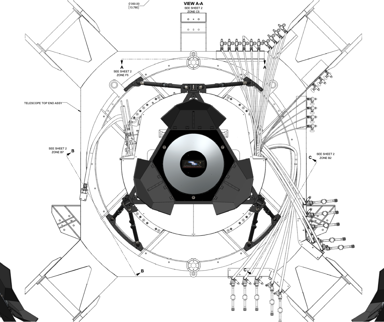
Fig. 1 Calibration Reflector#
The reflector was designed by Brian Johnson and was manufactured in the NOIRLab instrument shop in Tucson by Ron Harris, Anthony Tache and Anthony Borstadt. The cart was designed by Bill Schoening. The electronics were designed and built by Antanasia Jones. All testing was completed by Patrick Ingraham and Parker Fagrelius.
All drawings, mechanical and electrical, can be found on docushare, here: https://docushare.lsst.org/docushare/dsweb/View/Collection-15468
Mechanical Design#
The shape of the asphere is very specific, allowing an approximately f/4 beam to illuminate the 10 m-diameter calibration screen with uniform brightness.
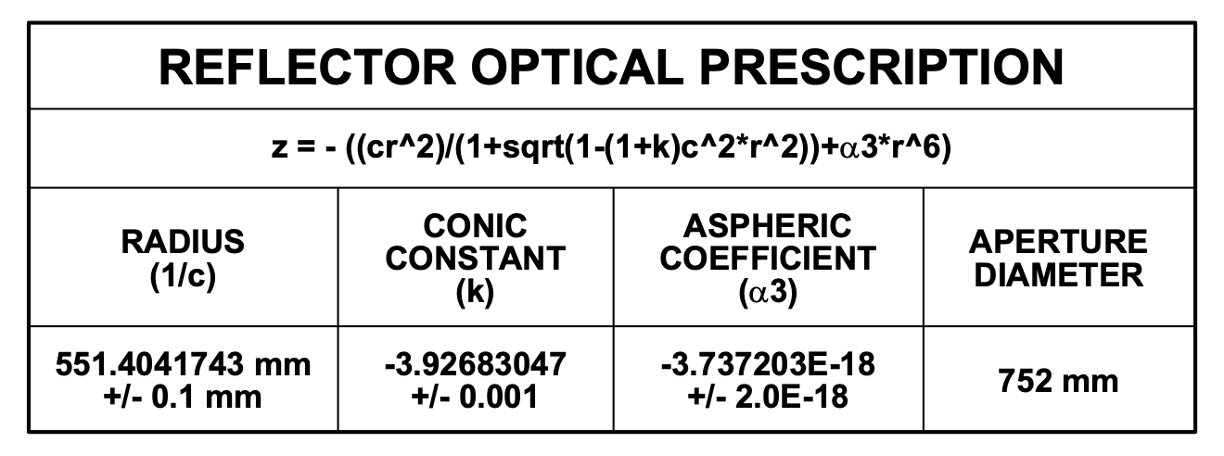
Fig. 2 Reflector Optical Prescription#
The optic was milled at the NOIRLab instrument shop, using a laser tracker to confirm the shape. The shape was reconfirmed in the lab.
There are three SMR’s attached to the optic that can be used to align it to the optical axis of the TMA. They are symmetrically placed around the Reflector.
There are three cover panels that can be opened and closed using CSC commands. Each panel is connected to a Firgelli Automations Optical Feedback Actuator (part #: FA-OS-35-12-18).
The mirror is attached to the top of the camera via six hexapod legs that extend over the pancake wrap. They are adjustable by hand so the Reflector can be aligned with the optical axis of the TMA. They are held to the structure with restrainer brackets so they can be easily attached to the reflector.
Electronics#
The electronics to open/close the covers are located in the electrical cabinet at the top end of the TMA (TEA-Cabinet 03). The rack is powered and connected to the TEA-AS-02 Port 2, with PDU port 3. The electronics were repackaged to accomodate the electrometer and other devices for the CBP Calibration System, also mounted on the TMA.
They are connected to the linear actuators via a single power cable.
Each of the three cover panels is attached to a linear actuator. These are all commanded together using Single-Pole Single-Throw (SPST) switches.
CIO0 is connected to SSR1 and SSR2 to open the reflector. CIO1 is connected to SSR3 and SSR4 to close the reflector.
The switches are commanded using a LabJackT4, which can be found at tea-reflector.cp.lsst.org
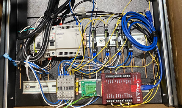
Fig. 3 Electronics used to open and close the reflector covers. This was the initial layout as found in the docushare documentation.#
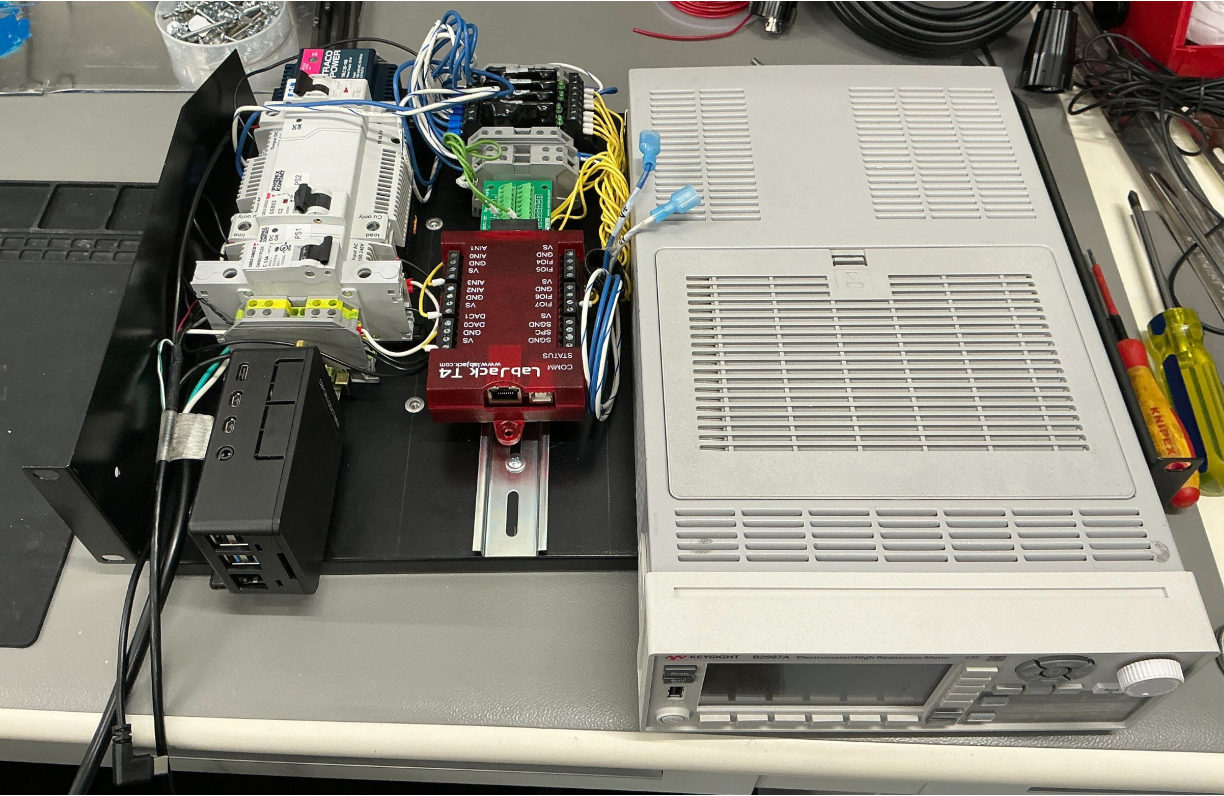
Fig. 4 Electronics for controlling the Reflector covers, packaged together with the CBP Calibration system electrometer and associated electronics.#
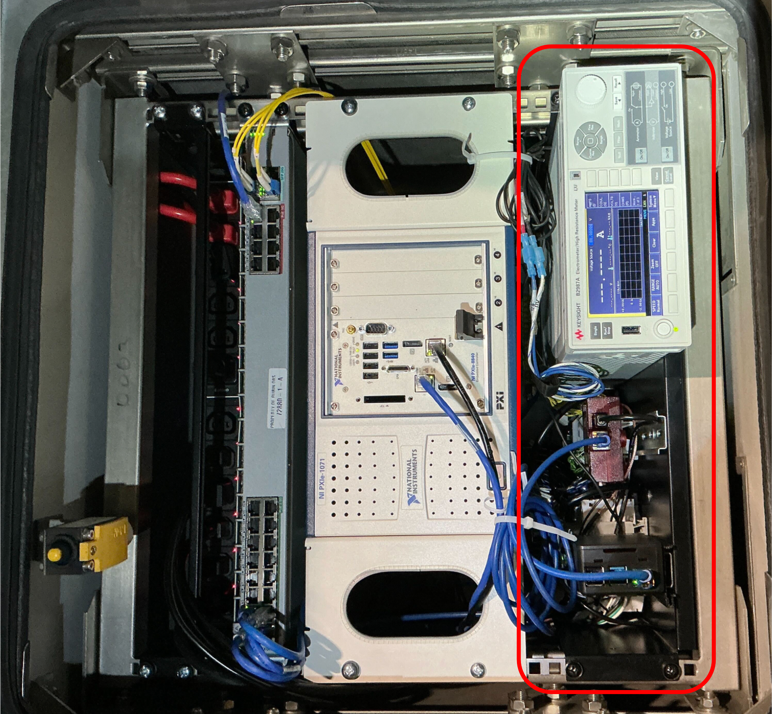
Fig. 5 Electronics as installed in the TEA-Cabinet 03.#
Remote Control#
If the LabJack and CSC are not working to control the Reflector covers, there is a backup approach. The power cable can be disconnected from the electronics cabinet and attached to the Linear Actuator remote controller box, which requires 12V power (see setup below).
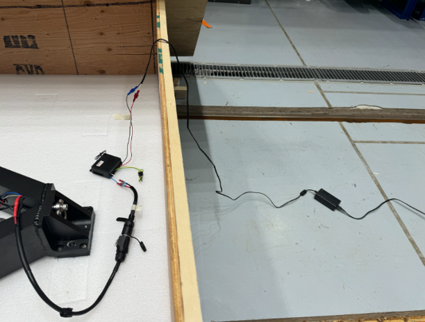
Fig. 6 Setup for using the remote control for the Reflector cover actuators.#
When this controller is connected to the Reflector, you should be able to use the small handheld remote (like for a garage) to open and close the reflector. These parts are connected to the triangle frame if needed.
Control Software#
The Reflector runs off of its own CSC, MTReflector.
There are essentially only two functional commands: open and close.
If you need to access the Reflector directly through the LabJack, you can use the Kipling App.
There is an Intel NUC in the laser cabinet with Kipling already installed, which you can access via Microsoft Remote Desktop at laser-powermonitor.cp.lsst.org (139.229.168.143).
Installation#
Prior to installation, it’s necessary to attach pairs of the hexapod legs with their respective restrainer bracket. The hexapod legs are not all identical, so care should be taken when pairing the hexapods, which are all labelled.
With the TMA at horizon, a manlift on L8 can be used to install the three hexapod leg pairs, attaching the feet of each hexapod as well as the restrainer bracket.
The Reflector can now be lifted with the overhead crane on its triangle frame and brought into place with the help of pins on the hexapod leg assemblies. The triangle frame can then be bolted to the hexapod legs.
The reflector must be removed whenever the camera is removed.
Cart#
Since the Reflector will need to be removed every time the camera is removed, a special cart was constructed for it. When the Reflector is to be removed, first unbolt the triangle frame and lower the reflector onto the cart. The hexapod legs can now be removed and also placed on the cart.
The cart and its tool box is stored on the 5th level, close to the camera lifting fixture.
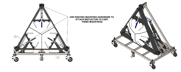
Fig. 7 Reflector cart, including a place for the triangle frame and hexapod legs.#
Alignment#
To achieve a flat and spatially uniform illumination of the Rubin Calibration Screen, the Calibration Reflector must be aligned with the optical axis of the TMA. Proper alignment ensures that light from the Flatfield Projector is reflected onto the screen without introducing gradients or geometric distortion. When the TMA is aligned to the calibration screen, the Reflector must then be aligned to the Flatfield Projector to maintain boresight consistency throughout the system.
The requirements for the alignment system are the following:
Projector aligned to Flatfield Projector
Tip/Tilt: 0.175°
Decenter: 2 mm
Reflector aligned to TMA optical axis
Tip/Tilt: 0.12°
Decenter: 1 mm
Three SMRs are mounted on the Reflector to enable measurements. The Reflector hexapod legs provide the degrees of freedom necessary to adjust tip, tilt, and decenter to achieve the required alignment.
In practice, we were unable to directly measure this directly during installation. During the period when the camera was installed at Level 3, the Reflector was test-fit and measured. These measurements indicated that the Reflector was aligned with the camera in accordance with the as-built documentation. Because the laser tracker installed on the TMA is capable of measuring the camera position relative to the telescope optical axis, it is inferred that the Reflector was correspondingly aligned to the optical axis.
Alignment between the Reflector and the Flatfield Projector was also established indirectly. The Projector location was measured relative to the calibration screen, and the screen location was subsequently measured using the TMA-mounted laser tracker. This measurement chain provides an inferred alignment of the Projector and Reflector to the telescope boresight.
The Reflector was not measured directly relative to the optical axis due to geometric constraints associated with using an external laser tracker outside the TMA. In the future, this limitation could be mitigated by employing two laser trackers operating within a common reference frame.
Evaluation#
Before shipping to Tucson, we measured the Reflectivity and Scattering properties of the Reflector. The average reflectance is about 80%, where fresh aluminum can have reflectance up to 91% on average. The higher levels of scattering are perhaps not surprising with the manufacturing of the optics
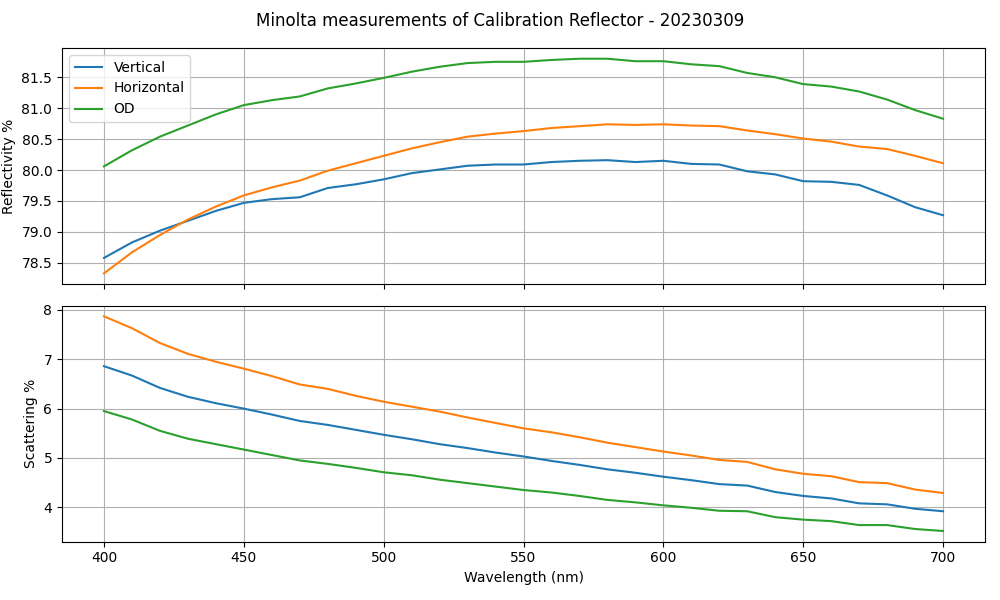
Fig. 8 Measurement of the reflectance and scattering properties of the Reflector while in Tucson.#
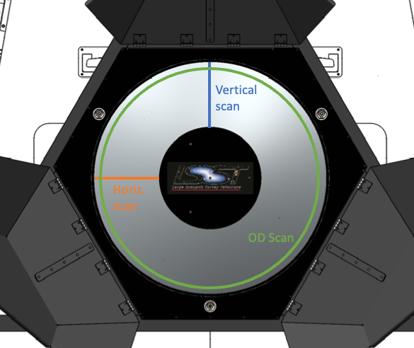
Fig. 9 Location of the measurements from the plot above#
The flatness of the optic, or rather its consistency with the desired asphere defined above, was measured during and after manufacturing. These measurements were made using a Hexagon Laser Tracker. We carefully touched the surface of the Reflector with a 1-inch retro reflector to get these measurements. The plot below shows the results from measurements made in 2018 and then in 2023. They match quite well, although the measurement errors seem to increase in 2023. It shows that the shape of the milled aluminum piece follows that of the asphere within approximately 10 µm, and potentially within 1 µm based on the initial measurements.
Fig. 10 Measurement of the Reflector relative to the definition of the asphere using the Laser Tracker#
Maintenance#
The reflector cover actuators are exercised daily during the Daily CalSys Checkout. Monthly, the mirror should be inspected and possibly cleaned.